PWheelRtView.tif: You can see the flow control valve at center-bottom. Each turn changes flow by same amount. The flow rate is shown by the dial coming off the pipe at that level or by the electronic flow meter with dial at top of this view. Flow comes in through the pipe coming down to the Pelton Wheel. The Prony brake unit seen on the right side of the system.
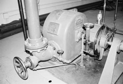
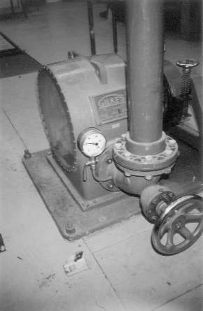
PeltonWheel&Prony.jpg: Apparatus connected to Pelton wheel. Inflow comes down the large pipe on thje left side of the photo. The flow rate is controlled by the valve below the pipe, which controls the needle valve in the inflow line. A small pip with a valve carries water to cool the Prony brake, which is a friction based control for the rotation speed. The force used to clamb the brake is measured (in our lab) by the force of the weights at the end of a level arm.
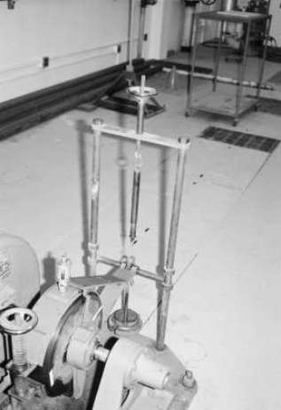
PeltonWeights.jpg: This view shows the system of weights on the lever arm used to measure the force acting on the Prony brake. There is a spring unit that pulls up to ballance the weights at the null point. The Pelton wheel causes the cent bar to rotate in what would be counter-clock-wise in this view. The weights pull it back to the null position. Power is force times the lever arm times the speed of rotation. The speed of rotation is measures either by a strobe light or by a gage attached to the rotating bar. Neither is installed in this view.
Pelton Splash1.jpg: This shows the Pelton wheel when little power is being produced. This looks like a very high speed of rotation, with much of the water going past the wheel and hitting the end of the unit.
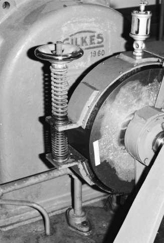
PeltonWheel2.jpg: Just the Pelton wheel is in this view. The glass section is just slightly in view. The small flow gage on the unit, the flow control valve, and the inflow supply pipe are the key items in this view. (I need to check for a better photo. This is a bit dark & has some clutter.)
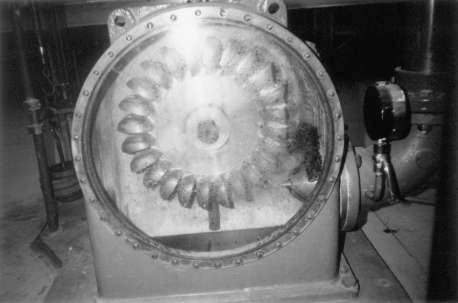
PeltonWheelStopped.jpg: Close view of inside of Pelton wheel. The bucket and the needle valve are seen. The dark section at the bottom of the glass is where the water drops out of the unit. The circle in the center is the bar connecting the Prony brake unit to the Pelton wheel. (Flash glare at top, but does not block view.)
PeltonWheel3.jpg: Prony brake unit from slightly toward the lab door. This has the mechanical gage to read rpm. The Prone brake tends to stall at lower speeds and can be difficult to read at those levels. But you need to get data for the full range of rpm values in every needle valve setting to give data for the plot of efficiency curves on the flow vs rpm graph.
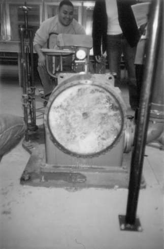
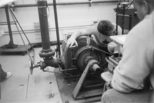
PeltonWheelRun1.jpg: Students making a run on Pelton wheel. One is tightening the Prony brake to bring the weights back to the poised position. Another has the strobe unit to read the rpm of the Prony brake. If you look closely, you can see a light curve on the brake unit that indicates where the strobe is not matched to the rotation speed.
PronyBrake.jpg: Close view of brake. It is stopped, and you can see the painted rectangle for the strobe to use in reading the speed of rotation. The brake unit is tightened or loosened to get the speed of rotation you want, as shown in the PeltonWheelRun1 view.