California State University, Sacramento CE 135 HYDRAULICS LABORATORY
Department of Civil Engineering
PELTON WHEEL TURBINE
REFERENCE:
Daugherty, R. L., and J. B. Franzini, 1977, FLUID MECHANICS WITH
ENGINEERING APPLICATIONS. 7th Ed., McGraw Hill Book Co. Chap.
14 and 15
Internet site:
Http:inventors.about.com/library/inventors/bl_lester_pelton.htm
American Society of Civil Engineers, Sacramento Section, 1976, HISTORIC
CIVIL ENGINEERING LANDMARKS Of Sacramento and Northern
California, p. 29: THE WHEEL THE WON THE WEST. TA 24. C2 A5
(Reference)
US Army Corps of Engineers, 1985, HYDROPOWER, EM 1110-2-1701,
Office of Chief of Engineers, Dept. of Army, Washington, D.C.
Turbines Convert Fluid Power to Mechanical Power
Machines that work on fluids are pumps, blowers,
compressors
Machines on which fluids work are turbines
Much of the same basic theory & similarity parameters work
for both pumps & turbines
The most comman turbines are reaction and impulse turbines
There are many types of reaction turbines
Most common in Central Valley are Francis & Kaplin types
Impulse turbines
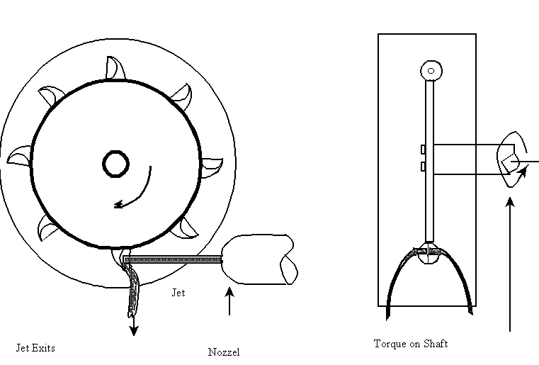
The turbine in Hydraulics Lab is a Pelton wheel
developed in the Sacramento Valley by Lester A. Pelton
high-velocity jet directed at buckets
normally used in conditions of low flow and high head
Pelton came to California for the gold rush
Became a carpenter and millwright
served his apprenticeship in Knight’s Foundry
Gold miners used water jets to blast the gold deposits from
the hillsides (placer mining)
Pelton experimented with ways to make the jets that the
miners used work as turbines
Splash from one blade of turbine striking next blade
slowed down turbine
Pelton devised a blade to split the flow so it went off the
side instead bouncing back
Pelton wheel turbine in our lab is basically the same as he
devised
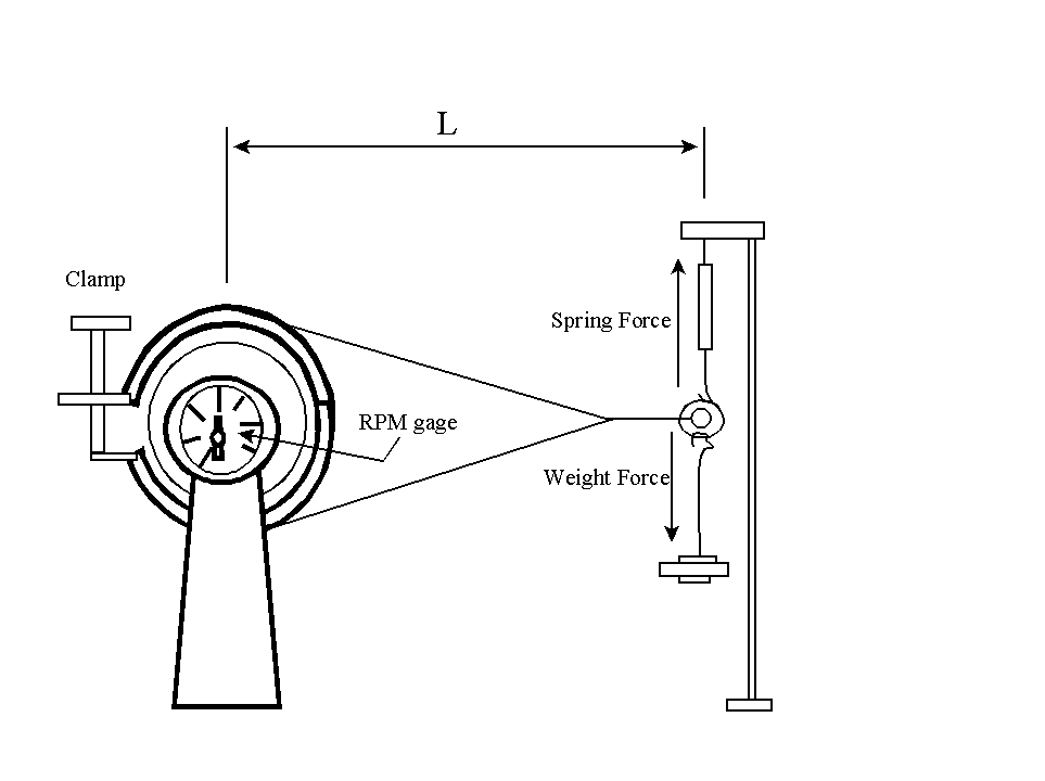
The Prony Brake
[To measure power that might go to a power network]
Invented in 1821 by French engineer Gaspard Prony
Applies an adjustable load torque to output shaft of a prime
mover (e.g. our turbine)
Power output is dissipated as heat in the braking material
Power output = torque * rotation speed,
Efficiency of Turbine = P0/Pw
P0 = Tω = 2πTN/60 in common English units
T = Torque on the shaft (ft-lbf)
ω = angular velocity (rad./sec.)
N = revolutions per minute
Pw = γQh = γQh/550 in common English units
γ = specific weight of water (lbf/ft3)
Q = flow rate (cfs)
h = energy head (ft)
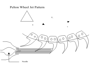
Power transfer from the water to the turbine wheel is a momentum transfer
Depends on the relative velocities between the fluid and the wheel
Too fast, the water velocity is too low for significant momentum transfer
Too slow, shaft speed is so slow that the power output is decreased
Theoretically, the optimum is when speed of bucket is half the speed of water jet
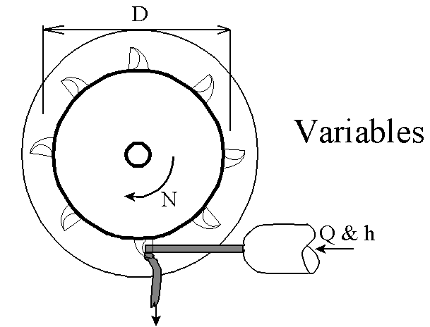
u = πDN/60
V = (2gh)0.5
φ = u/V is a dimensionless speed factor
In practice, the maximum efficiency φ just less than 0.5
PELTON WHEEL EXPERIMENTAL PLAN
EQUATIONS INVOLVED
Basic Equations
nS = N*P0.5/h1.25 = N(wQht/550)0.5/ht1.25
= (w/550)0.5 N Q0.5 / h0.75
v = (2ght)0.5 u = φv = πDN/60 and η = u/v
Thus, For Water
Q = 3.75E-4 (nS D/φ)2 ht0.5
For a Pelton wheel, nS ranges from about 2 to 8; so use 5
as a central value
φ ranges about 0.43 to 0.48; so use 0.45
Our Pelton wheel has D = 1 ft, so Q = 0.0463 ht0.5
Optimal efficiency points should be near
| For h= |
30 |
40 |
50 |
60 |
feet |
| Q |
0.25 |
0.30 |
0.34 |
0.37 |
cfs |
| N |
400 |
436 |
488 |
534 |
rpm |
PELTON WHEEL EXPERIMENT
GENERAL APPROACH
Select a Value For ht
Use range of Q & N above & below likely optimum points
Note: If pipe at pressure gage is 4 in. diameter, then for
Q = 0.4 cfs, you have v2/2g = 0.33 ft.
At this value, we can neglect this for planning the total
head for the sample data.
CALCULATIONS DURING THE EXPERIMENT
Primary objective of calculations is to assure that you have
the most efficient point included.
Power: Input Pw = γQ ht = 62.4 Q ht
Output Po = 2πNT/60 = L Fw N 2π/60
Efficiency: Po / Pw = k Fw N / Q
with k = 2π L / 60 γ ht = 0.002517/ht